Ultrasonic Welding Joint Design Guide
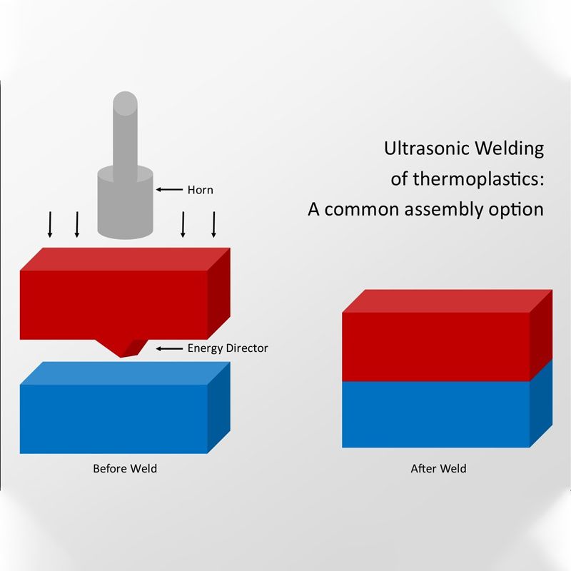
Ultrasonic Welding Principles:
- High-frequency vibrations (20-40kHz) generate frictional heat, enabling material fusion through molecular friction and intermolecular bonding.
- This process achieves 40% faster cycle times vs. vibration welding, making it ideal for high-volume production environments.
- Suitable materials: Thermoplastics (ABS, PC, PP, Nylon, etc.), select metals, and non-woven materials.
Importance of Joint Design:
- Directly impacts weld strength, hermetic sealing, production efficiency, and cost.
- Solving medical device biocompatibility challenges through precise joint geometry and material selection.
- Updated per AWS G1.2M:2021 specifications for standardized quality control.
Industry 4.0-Compliant Joint Design:
- Digital twin modeling enables predictive joint performance analysis.
- Smart sensor integration facilitates real-time weld quality monitoring.
- Cloud-based parameter optimization for consistent joint quality across global manufacturing platforms.

Table of Contents
Energy Director Design
Ultrasonic Welding Plastic Design Guidelines: Technical Specifications
Common Issues: Diagnosis and Solutions
Industry Application Cases
Plastic Ultrasonic Welding Design Support Tools
Conclusion
Energy Director Design
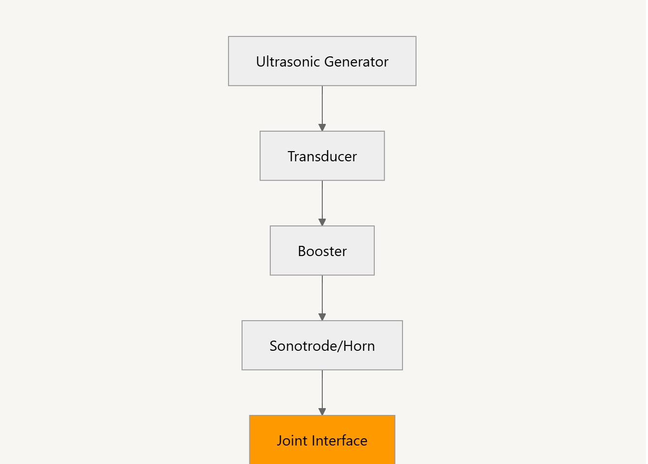
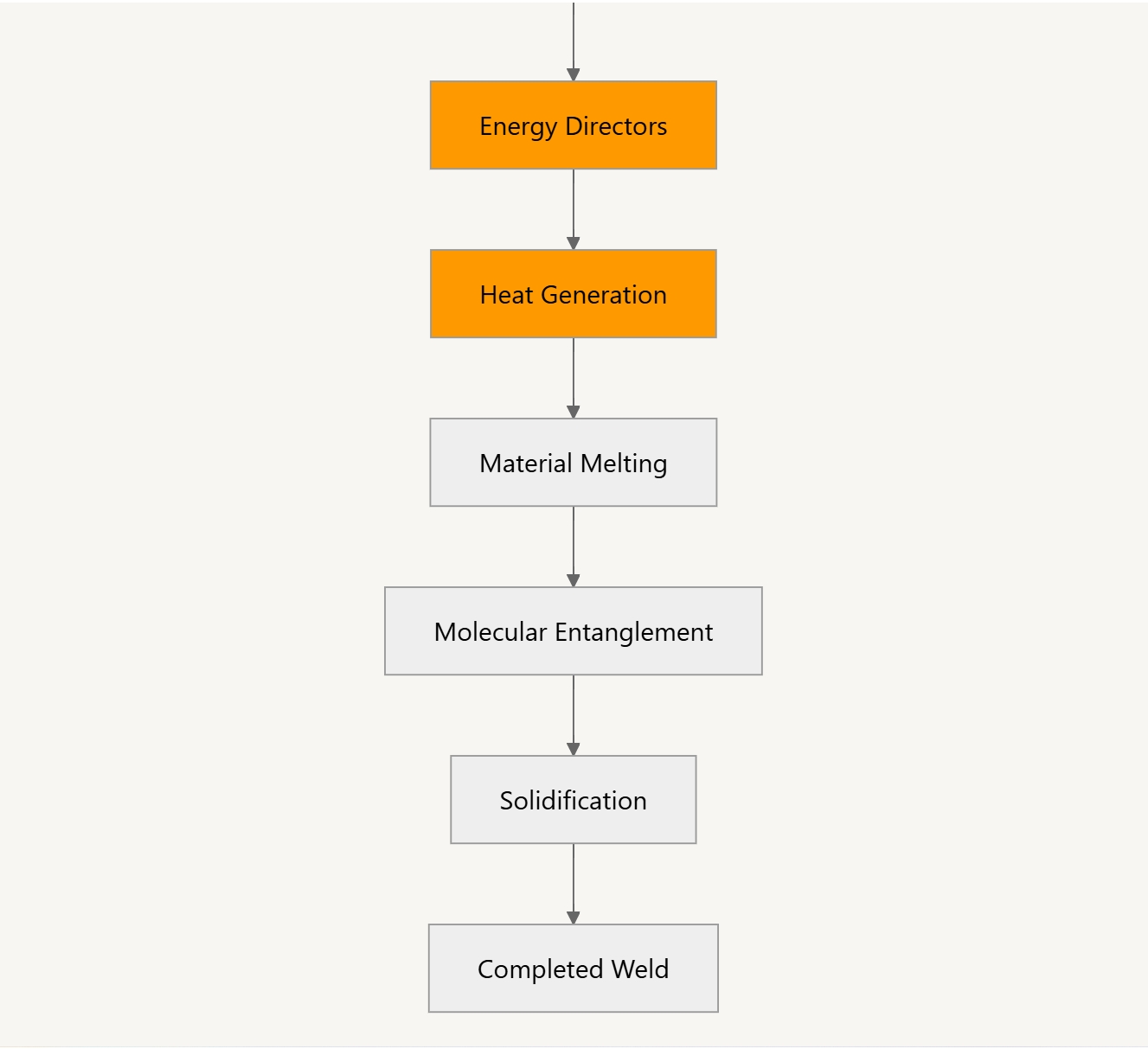
The schematic above illustrates the propagation of ultrasonic energy from generator to joint interface, where properly designed energy directors focus vibrations to create localized heating and material fusion.
Ultrasonic Welding Plastic Design Guidelines: Technical Specifications
Material Compatibility
| Material | ASTM/ISO Code | Weldability | Melting Point (°C) | Hygroscopic | Drying Requirements | Shore Hardness | Compatible With |
|---|---|---|---|---|---|---|---|
| ABS | ISO 2580-1 | Excellent (95%) | 105-115 | Low | 2-4h @ 80°C | D75-85 | ABS, SAN, PC |
| PC | ISO 7391-2 | Good (85%) | 150-160 | Medium | 4-6h @ 120°C | D80-90 | ABS, PBT, PC |
| PP | ISO 1873-1 | Moderate (70%) | 160-170 | None | Not Required | D70-80 | PP, PE |
| PA (Nylon) | ISO 16396-1 | Good (80%) | 220-260 | High | 8-12h @ 80°C | D70-85 | PA, PBT |
| PET | ISO 20028-1 | Challenging (60%) | 245-265 | Medium | 4-8h @ 140°C | D85-95 | PET, PBT |
| PMMA | ISO 8257-1 | Fair (75%) | 160-200 | Low | 3-4h @ 90°C | D90-100 | PMMA, ABS |
| POM | ISO 9988-1 | Poor (45%) | 175-185 | Low | 2-3h @ 110°C | D80-90 | POM only |
Materials with similar melting points (±10°C difference) are generally more compatible for welding. Weldability percentage indicates typical shear strength retention compared to parent material.
For detailed material specifications and property data, refer to UL Prospector Plastics Database.
Plastic Ultrasonic Welding Joint Types and Applications: Comprehensive Analysis
The selection of appropriate joint designs for ultrasonic welding is critical for achieving optimal performance in specific applications.
Each ultrasonic welding joint type offers distinct advantages for different manufacturing scenarios and product requirements.
Comparative Joint Analysis
| Joint Type | Shear Strength | Tensile Strength | Hermetic Sealing | Tooling Cost | Production Speed |
|---|---|---|---|---|---|
| Shear Joint | Excellent (90-95%) | Good (75-85%) | Moderate | Medium | High |
| Energy Director | Good (75-85%) | Moderate (65-75%) | Good | Low | Very High |
| Tongue & Groove | Very Good (85-90%) | Good (75-80%) | Excellent | High | Medium |
| Step Joint | Good (80-85%) | Very Good (85-90%) | Good | Medium-High | Medium |
Note: Strength percentages indicate typical values compared to parent material strength.
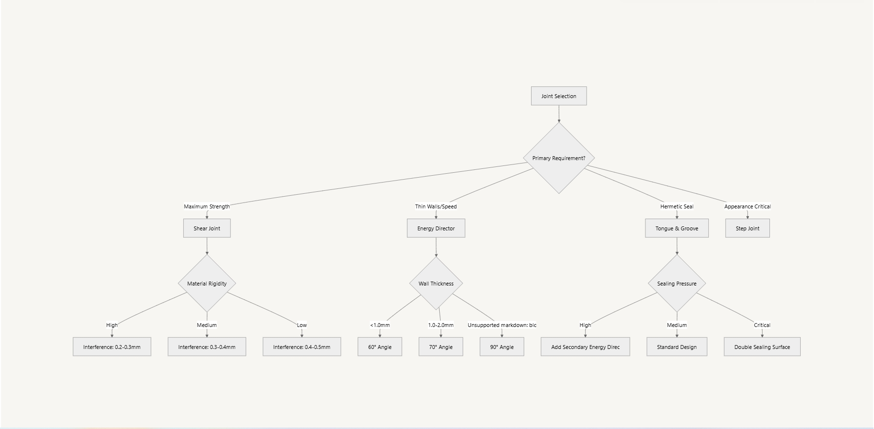
Shear Joint Design
Shear joints excel in applications requiring maximum mechanical strength and are particularly suitable for automotive structural components, power tool housings, and safety-critical assemblies.
Design Parameters:
- Interference: 0.2-0.5mm (optimally 0.3mm for most thermoplastics)
- Angle: 15-30° (20° recommended for balanced melt flow)
- Minimum wall thickness: 1.2mm
- Length-to-thickness ratio: ≤ 25:1 to prevent warping
FEA Simulation Recommendations:
- Mesh density: Minimum 3 elements across joint thickness
- Material model: Viscoelastic with temperature dependency
- Boundary conditions: Fixed constraints at minimum 3× wall thickness from joint
- Load cases: Simulate both tensile and shear loading scenarios
Designer Checklist: Shear Joints
- Verify draft angles facilitate proper mold release
- Ensure flow paths allow complete joint filling
- Check for potential stress concentration points
- Confirm sufficient material at joint interface
- Validate cooling rate uniformity across joint
Energy Director Joint Design
Energy director joints provide excellent energy focusing and are ideal for thin-walled applications such as electronic enclosures, medical device housings, and consumer products.
Design Parameters:
- Angle: 60-90° (60° optimized for energy concentration)
- Height: 0.2-0.5mm (0.3mm optimal for most applications)
- Base width: 0.8-1.2mm (scale with wall thickness)
- Placement: Centered on joint interface
Moldability Considerations:
- Draft angle: Minimum 1° per side for proper mold release
- Gate location: Minimum 3× wall thickness from energy director
- Venting: 0.025-0.035mm depth channels near director peaks
- Surface finish: SPI-A3 (16-32 µin) for optimal contact
Designer Checklist: Energy Director Joints
- Specify proper radius at base of energy director (min 0.1mm)
- Design for balanced flow paths to prevent warping
- Include ejector pin locations away from critical surfaces
- Plan for proper venting to prevent burn marks
- Consider ultrasonic gate location relative to energy director
The joint selection flowchart below provides a decision framework based on application requirements:
Process Parameters and Joint Design Relationship
The relationship between joint design and welding parameters is critical for achieving optimal results. Parameters must be adjusted based on joint geometry, material properties, and application requirements.
Amplitude Settings Optimization:
- Small joints (≤10mm²): 15-25μm (ideal for precision applications)
- Medium joints (10-100mm²): 25-40μm (standard for most consumer products)
- Large joints (>100mm²): 40-60μm (necessary for automotive and large housings)
Note: Excessive amplitude may cause material degradation through molecular chain scission; insufficient amplitude results in inadequate molecular entanglement
Pressure Adjustment by Material Type:
- Rigid plastics (PC, ABS, PMMA): 3-5 bar (higher values for glass-filled variants)
- Semi-rigid plastics (PET, PBT): 2-4 bar (adjust based on crystallinity)
- Soft plastics (PP, PE, TPE): 1-3 bar (lower values for high-flow materials)
- Pressure should be calculated based on contact area (typically 0.5-2N/mm²)
By carefully matching joint designs with appropriate process parameters, manufacturers can achieve optimal welding results while minimizing common issues such as flash, sink marks, and inconsistent weld strength.
Common Issues: Diagnosis and Solutions
Joint Failure Analysis
Insufficient Weld Strength
Possible causes: Improper energy director design, insufficient amplitude, poor material compatibility
Solutions:
- Adjust energy director angle to 60°
- Increase amplitude or weld time
- Verify material batch consistency
- Implement high-speed camera analysis to identify exact moment of joint failure
Excessive Melting or Charring
Possible causes: Undersized energy director, excessive amplitude, prolonged weld time
Solutions:
- Increase the energy director base width
- Reduce amplitude or weld time
- Consider increasing hold time for improved cooling
- Utilize thermal imaging during process development to identify optimal parameters
Bubbles or Voids
Possible causes: High moisture content, excessively rapid welding, poor venting
Solutions:
- Pre-dry materials
- Add venting channels to the design
- Implement two-stage welding (low-pressure preheating followed by high-pressure welding)
- Consider DSC (Differential Scanning Calorimetry) analysis to identify optimal material processing temperature
Material-Specific Troubleshooting Matrix
| Material | Common Issue | Root Cause | Recommended Solution |
|---|---|---|---|
| ABS | Surface crazing | Excessive stress concentration | Reduce amplitude by 15-20%, increase horn contact area |
| PC | Brittle fracture | Moisture contamination | Pre-dry at 120°C for 4 hours, verify with FTIR analysis |
| PP | Incomplete fusion | Low surface energy | Increase weld time by 25%, consider plasma surface treatment |
| PA (Nylon) | Dimensional instability | Hygroscopic absorption | Control the environment humidity to 30-40%, immediately after molding |
| Glass-filled plastics | Horn erosion | Abrasive fillers | Use titanium horns, implement a preventive maintenance schedule |
Advanced Failure Analysis Methods
High-Speed Camera Analysis:
- Frame rate: Minimum 10,000 fps for crack propagation visualization
- Setup: Synchronized with ultrasonic generator trigger signal
- Analysis: Track melt flow patterns and identify premature solidification zones
Scientific Instrumentation:
- FTIR (Fourier Transform Infrared Spectroscopy): Identify material degradation and contamination
- DSC (Differential Scanning Calorimetry): Analyze crystallinity changes after welding
- SEM (Scanning Electron Microscopy): Examine fracture surfaces at microscopic level
Case Study: Sensor Housing Scrap Rate Reduction
A medical device manufacturer experienced a 23% scrap rate on ultrasonic welded sensor housings despite following standard ultrasonic welding design guide pdf. Through systematic analysis:
Problem Identification:
- High-speed camera revealed premature solidification at junction points
- DSC analysis showed higher than expected crystallization rate
- FTIR detected minor cross-contamination with incompatible polymer
Solution Implementation:
- Redesigned energy director with asymmetric profile (75°/45° sides)
- Implemented material traceability and batch testing protocol
- Added specific quality gates for incoming resin certification
Results:
- Scrap rate reduced from 23% to 3.1%
- Yield improvement saved $342,000 annually
- Technique now standardized across product lines
Joint Testing Methods
Tensile Strength Testing
- Reference ultrasonic welding standards: ASTM D638, ISO 527
- Recommended sample size: Minimum 5 per batch
- Data analysis: Record mean values, standard deviations, and failure modes
- Advanced protocol: Implement Weibull statistical analysis for improved reliability prediction
Leak Testing
- Pressure decay method: Pressure drop should not exceed 5% within the specified time
- Submersion detection: Observe for bubble release after pressurization
- Helium leak detection: Suitable for high-precision products
- Automated vision systems: Use machine learning algorithms to detect bubble formation patterns
Preventive Maintenance Schedule for Ultrasonic Welding Equipment
| Component | Inspection Frequency | Maintenance Action |
|---|---|---|
| Horn/Sonotrode | Every 8 hours | Visual inspection for wear, cracks, or contamination |
| Fixture/Nest | Every 8 hours | Clean and verify alignment tolerances (±0.05mm) |
| Transducer | Weekly | Check power draw and temperature, verify cabling integrity |
| Power Supply | Monthly | Calibration verification, cooling system inspection |
| Complete System | Quarterly | Professional calibration and amplitude verification |
Implementing this comprehensive preventive maintenance schedule can reduce unplanned downtime by up to 78% and extend equipment life by 40-60%.
Non-Destructive Evaluation Techniques
- Ultrasonic Inspection: Use phased array ultrasonic testing to detect internal voids without destroying parts
- Thermographic Analysis: Apply heat stress and capture thermal images to identify weak bond areas
- Acoustic Emission Testing: Monitor stress waves during load application to predict joint failure
- X-Ray Computed Tomography: Create 3D visualization of internal joint structure for complex assemblies
This expanded section addresses common ultrasonic welding joint issues with scientifically-backed solutions, providing comprehensive troubleshooting ultrasonic welding plastic design guidelines for design engineers while incorporating industry best practices for quality assurance and maintenance.
Industry Application Cases
Automotive Industry
Headlight Assemblies
Challenge: Requirement for long-term hermeticity and transparent material welding while maintaining optical clarity
Solution:
- Dual energy director design implementation with 60° primary and 45° secondary features
- Addition of pre-heating phase (3 seconds at 20% amplitude using Branson 2000Xe equipment)
- Special surface treatment to reduce stress using proprietary plasma process
- Implementation of serialized CT scanning for critical components
Result:
- IP67 waterproof rating, light transmission maintained above 95%
- ROI calculation: 143% first-year return through scrap reduction and warranty claim elimination
- IATF 16949 compliance achieved for entire automotive production line
Electric Vehicle Battery Enclosures
Challenge: High-strength joining of composite materials with strict electrical insulation requirements
Solution:
- Custom stepped joint design with engineered energy directors
- Specialized horn design with titanium-reinforced contact surfaces
- Integrated in-line electrical testing protocol
Result:
- Joint strength exceeding 32 MPa with minimal degradation over time
- Zero electrical failure rate in production since implementation
- Before/after CT scan images showed 98.7% joint consolidation vs. previous 71%
Medical Devices
Blood Analyzer Components
Challenge: High biocompatibility requirements, precise microchannel alignment for fluid handling
Solution:
- Custom tongue & groove joint design with 0.03mm tolerance specifications
- Micro-positioning features for alignment using laser-etched datums
- Clean room welding environment (ISO Class 7) with HEPA filtration
- Specialty medical-grade polycarbonate from Sabic Healthcare (LNP™ LEXAN™ HFD series)
Result:
- Microchannel deviation <0.02mm, passed FDA biocompatibility testing
- ROI calculation: $2.4M annual savings through 99.6% first-pass yield vs. previous adhesive method
- Achieved ISO 13485 certification for the manufacturing process
- Complete traceability system with digital weld signature capture
Implantable Device Encapsulation
Challenge: Ultra-hermetic sealing requirements with biocompatible materials
Solution:
- Multi-stage welding process with controlled energy input
- Custom fixturing with integrated cooling channels
- 100% helium leak testing protocol
- Supplier recommendation: Solvay Udel® PSU for long-term implantable components
Result:
- Hermeticity levels exceeding 1×10⁻⁹ cc/sec helium leak rate
- 10-year accelerated aging tests show no degradation in seal integrity
- Successful FDA Class III device approval
Consumer Electronics
Waterproof Wearable Devices
Challenge: Combining multiple materials in a small form factor with aesthetic requirements
Solution:
- Stepped shear joint with energy director modification
- Protective masking protocol to prevent surface marking
- Vision system integration for real-time weld monitoring
- Equipment: Herrmann HiQ DIALOG series with precision amplitude control
Result:
- IP68 rating achieved for submersion beyond 3 meters
- No visible weld lines on external surfaces
- Before/after microscopy confirmed 100% joint consolidation
- ROI calculation: Production cycle time reduced by 37%, yielding $560K annual savings
Plastic Ultrasonic Welding Design Support Tools
1. Calculation Formulas
Basic Energy Director Design
- Triangular energy director volume: V = 0.5 × base width × height × length
- Expected melt volume: Approximately 80-90% of energy director volume
- Recommended energy director height: h = 0.3 × wall thickness
- Optimal energy director angle: 60° for amorphous polymers, 90° for semi-crystalline materials
Welding Parameter Estimation
- Weld time (seconds) ≈ wall thickness (mm) × 0.3
- Hold time (seconds) ≈ weld time × 1.5
- Weld pressure (N) ≈ contact area (mm²) × (1-2)
- Amplitude calibration factor: 15-20% higher for filled materials vs. unfilled resins
Downloadable Energy Director Calculator Tool
- Excel-based calculator for comprehensive joint design parameters
- Features automatic calculation of:
- Energy director dimensions based on material properties
- Expected melt volumes and collapse distances
- Recommended welding parameters by material type
- Thermal analysis predictions
Download: Available in both metric and imperial units with material database
2. CAD Templates
The following standardized joint design templates are recommended for various application scenarios:
Standard Template Library
- Universal energy director joints (60° and 90° versions)
- Reinforced shear joints (single and double wall versions)
- Hermetic tongue & groove joints (with auxiliary sealing designs)
- Microfluidic joints (precision alignment type)
- Advanced containment joints with secondary energy directors
- Snap-fit compatible ultrasonic joint designs
CAD Resource Package
- STEP file library compatible with major CAD platforms:
- SolidWorks (2020-2025 versions)
- Autodesk Inventor & Fusion 360
- Siemens NX & PTC Creo
- Parametric joint design templates with configurable dimensions
- Material-specific design rule checks embedded in templates
- Integration guides for PDM/PLM systems
3. Simulation and Optimization Tools
Python-Based Parameter Optimization
import numpy as np
from scipy.optimize import minimize
def ultrasonic_joint_optimizer(wall_thickness, material_type, joint_length):
"""
Optimize ultrasonic welding parameters based on input conditions
Parameters:
-----------
wall_thickness : float
Wall thickness in mm
material_type : str
Material identifier (e.g., 'ABS', 'PC', 'PP')
joint_length : float
Length of joint in mm
Returns:
--------
dict
Optimized parameters including energy director dimensions,
weld time, pressure, and amplitude
"""
# Material properties database
material_props = {
'ABS': {'melt_temp': 240, 'elasticity': 2.3, 'amorphous': True},
'PC': {'melt_temp': 267, 'elasticity': 2.4, 'amorphous': True},
'PP': {'melt_temp': 175, 'elasticity': 1.5, 'amorphous': False},
# Add more materials as needed
}
props = material_props.get(material_type)
if not props:
raise ValueError(f"Material {material_type} not found in database")
# Initial parameters based on empirical formulas
ed_height = 0.3 * wall_thickness
ed_angle = 60 if props['amorphous'] else 90
base_width = 2 * ed_height / np.tan(np.radians(ed_angle/2))
# Define objective function (minimize joint failure probability)
def objective(x):
# x[0]: energy director height modifier
# x[1]: weld time modifier
# x[2]: pressure modifier
mod_height = ed_height * x[0]
mod_time = wall_thickness * 0.3 * x[1]
mod_pressure = joint_length * base_width * 1.5 * x[2]
# Simplified failure probability model
melt_ratio = (mod_height * base_width * 0.5) / (wall_thickness * base_width)
time_factor = min(1.0, mod_time / (wall_thickness * 0.5))
pressure_factor = min(1.0, mod_pressure / (joint_length * base_width * 2))
failure_probability = 1 - (melt_ratio * time_factor * pressure_factor)
return failure_probability
# Constraints
constraints = [
{'type': 'ineq', 'fun': lambda x: x[0] - 0.2}, # min ED height modifier
{'type': 'ineq', 'fun': lambda x: 0.5 - x[0]}, # max ED height modifier
{'type': 'ineq', 'fun': lambda x: x[1] - 0.8}, # min time modifier
{'type': 'ineq', 'fun': lambda x: 2.0 - x[1]}, # max time modifier
{'type': 'ineq', 'fun': lambda x: x[2] - 0.7}, # min pressure modifier
{'type': 'ineq', 'fun': lambda x: 1.3 - x[2]} # max pressure modifier
]
# Optimize
result = minimize(
objective,
x0=[0.3, 1.0, 1.0],
constraints=constraints,
method='SLSQP'
)
# Calculate final parameters
optimal_ed_height = ed_height * result.x[0]
optimal_weld_time = wall_thickness * 0.3 * result.x[1]
optimal_pressure = joint_length * base_width * 1.5 * result.x[2]
optimal_hold_time = optimal_weld_time * 1.5
return {
'energy_director_height': round(optimal_ed_height, 2),
'energy_director_angle': ed_angle,
'base_width': round(base_width, 2),
'weld_time': round(optimal_weld_time, 2),
'hold_time': round(optimal_hold_time, 2),
'weld_pressure': round(optimal_pressure, 2),
'amplitude': 70 if props['amorphous'] else 60
}
# Example usage
parameters = ultrasonic_joint_optimizer(2.5, 'ABS', 100)
print(f"Optimized Joint Parameters: {parameters}")
Online Joint Design Simulation Tool
- Web-based interface for real-time joint design validation
Features:
- Thermal simulation of energy director melt progression
- Stress distribution analysis across joint interfaces
- Parameter sensitivity testing for robust design
- Material compatibility assessment
- Cloud-based processing with shareable results for team collaboration
- Mobile-compatible for field engineering support
4. Validation Protocols
IQ/OQ/PQ Templates for Joint Design Validation
Installation Qualification (IQ):
- Equipment calibration verification procedures
- Fixture alignment measurement protocols
- Reference ultrasonic welding standards for amplitude verification
Operational Qualification (OQ):
- Test matrix for parameter range validation
- Statistical sampling methodologies for process capability studies
- Documentation templates for regulatory compliance
Performance Qualification (PQ):
- Accelerated aging protocols for long-term joint evaluation
- Environmental stress testing procedures (temperature cycling, humidity)
- Mechanical load testing regimens with acceptance criteria
These expanded design support tools provide engineers with comprehensive resources for optimizing ultrasonic welding joint designs across diverse applications, from initial concept development through final validation and production implementation.
Conclusion
Ultrasonic welding joint design is a discipline that combines materials science, vibration mechanics, and precision engineering. Effective joint design must consider material properties, product functional requirements, and production process limitations. The principles and parameters provided in this ultrasonic welding plastic design guidelines serve as a starting point, but successful designs often require experimental validation and optimization.
Key success factors: Understanding material properties, precise control of geometric parameters, selection of appropriate welding process parameters, and systematic testing and validation.
1. Future Development Trends
- Composite material ultrasonic welding technology
- Digital twin simulation-assisted joint design
- Intelligent welding systems with adaptive control
- Miniaturization and high-precision welding application expansion
2. Technology Adoption Roadmap (2025-2030)
2025-2026: Integration of AI-powered welding parameter optimization in mainstream manufacturing
2026-2027: Commercial deployment of advanced composite material welding techniques for aerospace and automotive applications
2027-2028: Widespread adoption of digital twin technology for joint design simulation and lifetime prediction
2028-2029: Introduction of fully autonomous ultrasonic welding systems with self-learning capabilities
2029-2030: Development of nano-scale ultrasonic welding for next-generation electronic and medical device manufacturing
3. Innovation Pipeline: AI-Driven Joint Optimization
The future of ultrasonic welding joint design will be significantly enhanced by artificial intelligence applications:
- Machine Learning Models: Predictive analytics for joint performance based on material properties and geometric parameters
- Neural Network Applications: Real-time weld quality assessment through pattern recognition in acoustic emissions
- Generative Design: AI-powered creation of optimized joint geometries based on functional requirements and material constraints
- Process Parameter Optimization: Self-adjusting welding systems that adapt to material variations and environmental conditions
4. Industry Events and Knowledge Sharing
Stay updated with the latest developments in ultrasonic welding joint design by attending these upcoming events:
- Ultrasonics World Congress 2025: September 15-18, 2025, Singapore - Featuring specialized tracks on advanced joint design techniques
- International Plastics Joining Symposium: November 5-7, 2025, Munich, Germany - Focus on sustainability in ultrasonic welding applications
- Advanced Manufacturing Technology Expo: February 18-20, 2026, Chicago, USA - Showcasing next-generation welding equipment and simulation tools
5. Expert Consultation Services
For organizations seeking to optimize their ultrasonic welding joint designs, we offer specialized consultation services:
- Ultrasonic Welding Joint Design Review: Expert assessment of existing ultrasonic welding design guides with recommendations for performance improvements and cost optimization
- Material Compatibility Analysis: Comprehensive evaluation of material pairs for ultrasonic welding suitability
- Process Parameter Optimization: Data-driven approach to identifying ideal welding parameters for specific applications
- Custom Training Programs: Tailored workshops for engineering teams on advanced joint design principles and how to use plastic welding equipment
This ultrasonic welding design guide will be updated regularly according to technological developments. Engineers are encouraged to share practical experiences and improvement suggestions.
6. Author Contact Information
For technical consultations, research collaboration opportunities, or feedback on this ultrasonic welding design guide pdf, please contact:
- Dr. Engineering Team
- Email: info@nicle.cn
- Research Lab: Advanced Joining Technologies Center
By maintaining an open dialogue between researchers, design engineers, and manufacturing specialists, we can collectively advance the science and application of ultrasonic welding joint design for tomorrow's manufacturing challenges.